Sound Design Live eBook

Posted July 25, 2013 by 6o6
Categories: Live Sound, Sound Systems Book

Tags: , ,

I recently wrote the forward for an eBook that Nathan Lively has published called Sound Design Live: Build Your Career As A Sound Engineer. It’s a great read and I’ll include the forward below.

* * *

sound-design-live-ebook-coverAudio engineering technology has changed, but the work is still all about connections. Not through CobraNet®, Dante or AVB but rather the personal connections of telephones, email, social media and old-fashioned face to face. Connecting to creative artists, crew, managers, producers and audiences. If you are already in this field you are somewhere in this interconnected network. If you are wanting to get involved, welcome to the ultimate work in progress. This book is all about connections and why they are the most important, valuable and motivating forces in the industry. Nathan Lively plays the role of network hub and monitors traffic in this book to give you a glimpse into the absolutely real experience of our peers and mentors in this trade. The voices in this book have vastly different viewpoints, passions, and experience. Artists who use technology for self-expression, technologists who thrive on being a conduit for artists to reach their audience, and folks who have worn many different hats. If Nathan had brought them all together in one room to discuss audio, there would be at least as many passionate disagreements as points of concordance. Two points they would all agree on are the importance of having a passion for this field of work and attention to networking and relationships. So much of this field is serial monogamy, and therefore we must be careful to maintain good relationships, not burn bridges and keep that little black book up to date with all the folks you might want to see in the future. This book examines the relationship issues that are so important for getting into, and staying in, this business.

Nathan’s choice of speakers and topics provides a mix of information and experiences that I have not seen collected in one place. The viewpoints are refreshingly honest and free of the laundry lists of gear that characterize 90% of words written about this field. These are not all superstar designers with mega-million dollar projects. Dive bars, home studios, educators, starving artists and manufacturers are here as well. The contributors are very real people in whom it is impossible not to see a part of yourself, just as much as it impossible to not find a viewpoint that you had never considered or understood before.

Nathan’s “Sound Design Live podcasts” have brought these people’s voices to the internet and will continue to do so in the future. Here and now is a collection of assembled wisdom and experience that I believe will open your mind to the many ways you can expand your role in the audio professional network.

SVC online – Array or not to array: Part 1 – Additional data

Posted April 4, 2012 by 6o6
Categories: Line Array, Live Sound, Point Source Array, Speaker Array

At long last I have found some time to post here again. Well actually I don’t have the time but I did it anyway. The thing is – I left a trap in an article I wrote that would force me to make time here – and it worked!   This will be brief – or I ‘ll never get it done.

I wrote an article for Sound Video Contractor – about arrays. Click on the link and you can read it. It ended up being more in-depth than I originally planned and so it will be a two-part affair. And actually it is more in depth than even that so I have elected to post some of the data files here  – since it was just too much for a mag article.

This post contains data related to figures 3-5 in the article. What is discussed there are 8 different ways to 80 degrees of coverage – 1 box, 2,3,4,8,16,16 and finally 40 boxes. The trick here is that if you take 80 degrees and divide it by the number of boxes – you will see the splay. For example 2 boxes splayed at 40 degrees, 3 at 27, 4 at 20 etc.  The splay angle is critical but the coverage angle of the individual element plays a major part also – especially at lower quantities. case in point – the two x 40 degree array uses 2 40 degree boxes at 40 degrees. The 3x array uses 3 boxes that are 30 deg each, splayed at 27. As the quantity rises we can see that the role of the individual element becomes overwhelmed by the splay angle. In the case of the 40 box array the splay angle is 2 degrees (40 x 2 = 80 deg) but the box is a 10 degree box. The fact that this individual box is 10 degrees is not apparent in the combined shape – which makes a very sharp 80 degrees.

The complete set of data shows 10 octave resolution plots for each of the eight arrays.  All of the speakers are front-loaded woofer except for the 3 box array (which is the LF and HF horn-loaded Meyer MSL-4). Therefore it’s low frequency response is an outlier because its individual response is so much narrower than the others.  The single box, 2,3,4 and 8 box arrays use 2-way elements with relatively constant beamwidth horns.  The 16 and 40 box scenarios use line array type speakers, whose directionality increases with frequency. There are two 16 box scenarios: 16a is a smaller box with wider individual angle than the 16b ( a larger box with around 1/2 the individual angle. This was done to help demonstrate the similarities and differences when we use the exact same quantity and same splay angles but start from different elements.

Some of the trend lines to note here – you can see that from 4 kHz on up the coverage pattern is 80 degrees for ALL of the 8 scenarios. The shape of the 80 degrees can vary considerably.The single unit has the most gradual rate of loss over angle, whereas the 40 speaker versions maintains 0 dB for virtually it entire angular spread and then finally drops off like a cliff. As a continuum we can see the following trend: increased quantity  and smaller splay creates sharper edges. The dominant feature in the high quantity/low splay angle arrays is a high percentage of angular overlap. The small quantity/large splay angle arrays have low overlap, and also have softer edges. If we just look at this as a simple spreadsheet of HF coverage angle, then we see 80 degrees across the board. On the other hand, when you look at the coverage SHAPES, you see a great deal of contrast as to how the 80 degree shaper is filled.

As we move down through the midrange (250-1kHz) we see substantial variations in both shape and defined coverage angle. The array show a similar pattern where the coverage narrows and then widens below. This leaves each array with a 3-part response: expanding wider at the low end, a small transition range where the pattern narrows in the midrange, followed by a steady coverage angle above.  The frequency range where the narrowing occurs falls with rising quantity and size  (e.g. the mid-sized 2-box array constricts at 500 Hz, the larger 3-box at 125 Hz. The smaller 16 box array tightens at 125 Hz, while the larger 16 box arrays does the same an octave lower.

The last feature is the runaway low end. As quantity and size go down, the break frequency goes up. This can be easily seen by the lines flying into the top of the graph (which finishes at 180 deg). The 40 box array is the last to budge, only expanding to 100 degrees by 31 Hz.  Have fun rigging that!

In conclusion: isolation summation is the dominant shaping force in the high end – and this is why the shape stays a consistent 80 degrees. Overlap is the dominant shaping force in the low end. The higher quantities have more overlapping elements to bring to the party and therefore enjoy a wider range and more uniform LF beam width. The squeeze point in the response is the transition zone between these dominant shape factors.

This post is pretty brief – but bear in mind that this is a add-on to the article. Together they should hopefully make some sense.

Thanks for your time. Comments are welcome

And here are the files:

Beamwidth chart for single speaker and all array configurations


___________________

Next is the MAPP plots for all the speakers in the following order (I was not able to outwit the computer and get them in the order i wanted……

1) 16  10 deg speakers at 5 deg – small (Mina)

2) 16 5 deg speakers at 5 deg – large ( Milo)

3) Single  80 deg Speaker (CQ-1)

4) 2 x 40 degree speakers at 40 deg (UPA-2P)

5) 3 x 30 deg speaker as 27 deg (MSL-4)

6) 4 x 20 deg speaker at 20 degree (JM-1P)

7) 8 x 10 deg speaker 10 deg (Mina)

8) 40 x 10 degree speaker at 2 deg (Mina)


Earthquake video of our sound system at Tokyo Disney Sea

Posted March 13, 2011 by 6o6
Categories: Alignment & Design, Live Sound

Here is a video from Tokyo Disney Sea taken during the quake. It was sent to me by Matt Ferguson. This sound system was designed by Roger Gans, Mike Shannon, myself and also Bill Platt. Also involved on the audio side were Richard Bugg, Francois Bergeron, Martin Carillo, and many others. We had strict design limits on the poles regarding weight – for wind and ….you got it. Each of the poles is retracted inside a chamber and then hydraulically expanded twice a day for day-time and night-time shows. This was the day show.

Here is a picture of the interior of one the speaker vaults. The speakers are already up and out at this point.  We had different sizes of poles for different areas because some locations did not needs as many speakers. Of the poles shown in the video, only the lighter weight unit goes down – but there are 44 poles total so I have no idea about the rest.

It is worth noting that alot of time and effort was put into the emergency announce capability of the system. This was something that book the Japanese and Disney engineers kept very much in focus. The announcements that you hear on the video were done in advance and loaded on to a “360” sample playback device. It was necessary to allot 30% more time for Japanese language of an equivalent phrase in English.

We played those samples MANY times through all sorts of contingency scenarios. It was a good feeling to see it come through when it really counted.

Speaker enclosure at Tokyo Disney Sea

LR Mains+Downfill

This is one of the big poles. 21 ft total

Some big poles with rehearsing boats

Here are a couple of the poles during a boat rehearsal.

Big pole -Speakers with lighting

In the big scheme of things this is very small. I was happy to see the buildings holding up there. I wish for the safety and speedy recovery for everyone there.

6o6

Poll results are in for the cable test

Posted March 13, 2011 by 6o6
Categories: General, Live Sound

So it looks like 78 people took the survey. Here are the preliminary results on John Huntington’s site.  I have long ago given up any fantasies that I am a Golden Ear. My response to listening to these tracks was that I could not hear any difference. From the survey results it looks like either (A) even Golden Ears can’t tell, because…..uh…… we can’t tell, (B) John bought horn cables and then used a piano for the source. If he had used piano cable we would have heard the difference.

Ahhh… Don’t get me started!

But just one thing……For me, the DEAD giveaway on the VooDoo Magic nature of this topic is when people start talking about cable cleaning up the midrange…. “midrange mud” etc.  MIDRANGE!   That would be the part of the cable’s response that would be the same with 24 AWG or 2.4 AWG. That would be the part of the response left unchanged between the long jump and the marathon distances.

If there was really a dramatic difference in our VERY low electromagnetic frequencies of audio between wire twisted this way – or that (just because we work a gig doesn’t mean we hear a gigahertz) ,  then think of the HUGE the difference there would be between a 1 meter and a 10 meter cable. OMG there is 10x as much wire length!  That would be NIGHT & DAY if the real world spun on the axis of the cable marketeers.  Now we know the REAL reason the Left and Right in our PA never quite match!

If you want to REALLY fix midrange mud these are some of things that might help: Turn down the monitors. Isolate the mics. Put some curtains up. Put in a midrange filter and cut. Point the speakers in the right place. Splay the speakers apart. I could write a book on it……

If you want to talk about the audio properties of cable AT LEAST center the discussion around the parts of the audio spectrum that may actually be affected by the differences in wiring topology: the extremes.

Oh crap…I got started. I’ll stop now before I really get started…..

PS: I got a much bigger difference from Pre-Beer to Post-Beer than between A and B. 🙂

6o6

The Emperor’s New Stereo

Posted March 9, 2011 by 6o6
Categories: Alignment & Design, Live Sound, Studio and Cinema

I was contacted a few months back by Jose Luis Diaz about an article I wrote for Mix magazine -in 1998. He asked did I have a copy of the original in pdf form.  No. I am not the best archivist. 😦

Well it turns out he had a Spanish translation of it and he RETRANSLATED it back to me. 🙂

It’s funny for me to see the old article and the extremely crude drawing quality of that era. As for the subject matter itself, it still holds up pretty well. Not too long ago went to another concert with a 5 piece jazz band where the piano was on the left and the guitar on the right. We had really great seats on the left side. The piano and drums and bass were fresh and clear. The guitar I heard when it came back off the wall on the right side. Bet it sounded great at FOH.

So here it is ……once again.  And if you want the Spanish version go here

**********************************

The Emperor’s New Mix

Unveiling the stereo myth on live sound

(Bob McCarthy Mix Magazine January 1998)

Once upon a time, there was an emperor living in a giant palace.

After mixing some tracks in his private studio, the emperor was so happy with the stereo image that he decided to throw a concert for his 5000 closest friends.

For the occasion, he bought a new luxuriously advanced stereo sound system.

Before the show started, the emperor told the audience what the sound system sales man had said to him:

”This system has such magic qualities, that it’s capable of creating perfect stereo imaging in every seat. Every person that doesn’t experiences stereo imaging is, obviously, vulgar and not suitable for his job.”

Everyone was sitting to the left and to the right all along the center walkway.

The sound system was set in such a way, that all the seats where inside the left and right P.A. towers coverage area.

The concert began.

The emperor was sitting in the center of the room, and he marveled at his own sophistication. The stereo image was perfect!

Everyone else shuffled in their seats realizing how vulgar they were and the danger they faced of losing their jobs if they were caught. To them, the sound appeared to come almost exclusively from the nearest P.A tower from their location.

When the concert finished, all the guests congratulated the emperor over the vivid stereo image they had experienced. Everything seemed to go well until a little boy, putting words to everyone’s thoughts, said:

”Why did all the music except the tom drum come from the right speaker?”

What the boy had said was true, and everyone knew it.

For some reason, the stereo image only worked in the very center of the room. How could this be? Was there something wrong with the sound system? With the mix? With the room acoustics? None of the above.

STEREO IMAGING IS NOT SCALE-TRANSFERRABLE

There is one simple and irrefutable problem: stereo effects don’t scale when moved from a studio to a bigger room. You could have all the stereo coverage needed for every seat, but that doesn’t mean you’ll experience stereo imaging when you leave the center.

Everyone agrees that stereo spatialization is better perceived from the center. But in a studio, or in a living room, one can move freely over a large part of the room and still experience reasonably effective stereo.

Try it yourself: Play a well mixed track in your living room, sit directly in front of the left speaker and close your eyes. Although off-centre, it’s still possible to identify the instruments all along different horizontal locations in between speakers. Now try it again in front of the P.A tower of the left, from a 30 meters distance in a concert hall. No more gradual horizontal movement between both sides. The image stays almost exclusively in the left speaker.

Keep your eyes closed, and slowly head to the center of the room (be careful!) until you reach a point where you find the same panoramic image you experienced in your living room. Be objective! This is all about real experience, not expected results. Surely, you will be standing just a few steps away from the center of the room, not much further than in your living room.

The distance you can travel in your living room while retaining acceptable stereo imaging is almost the same as you can travel in a 5000 seat concert hall before you lose spatialization.

TIME AND INTENSITY DIFFERENCE

Panoramic location between two sound sources depends on two interrelated factors: Time differences and Intensity differences. Let’s analyze intensity differences first.Turn gradually the pan pot in your console to the right. You have created now a difference in the level between the channels, favoring the right one, thus, the stereo image (as it’s expected) moves to the right.

This happens, as long as you remain seated in the center of both speakers. If, by any chance, you’re sitting to either side, the image won’t move the same way the pan pot does. Why? Here comes the defining factor in sound localization: time difference.

We locate the image depending on which source arrives first to our ears, even if the time difference is minimal and the later source has more intensity. The psychoacoustic relation between these two factors is known as ”Precedence effect” and was analyzed in 1950, among others, by the now famous Dr. Helmut Haas.

The ”sweet spot” for binaural localization (stereo imaging) is within the first millisecond of time difference. If the time difference exceeds the 5 milliseconds, the sound image can only be moved by brute force. The channel that arrives last must be 10 dB louder than the first to achieve this.

Now this is where the scale concept really comes alive.

Time and intensity differences don’t translate equally when we scale from a small space to a large one.

The intensity difference is a proportion between the level of both sources (the two speakers, the two channels…). The intensity relationship between left and right channel is the same in your living room than in a stadium. If you’re standing at twice the distance from one speaker in reference to the other, the intensity difference will be 6 dB, This will remain the same, no matter if the difference is 1.5 and 3 meters, or 15 and 30 meters.

The time difference, however, is not a proportion. It is simply, the DIFFERENCE in the arrival time of both sources.

While the intensity difference was kept constant in the previous example, the time difference will be multiplied by 10 when we increase the distance from 1.5 (4.4 ms approx.) to 15 meters (44 ms).

Given that the time difference is the predominating factor in sound location, you can clearly see that the odds are low when you’re trying to achieve stereo in large scale.

Because we only have a 5 ms window to control the image, the usable space to recreate stereo in a stadium is, in proportion, really small compared to your living room. In other words, the horizontal area needed to experience true stereo localization (the space where the images can be situated) is barely larger in a stadium than it is in your living room.

Nobody wants to admit that there is no stereo for the big crowds. From a mix engineer point of view, stereo represents an advantage. If he is mixing from the center of the room, it’s easier to listen individually to each instrument in the mix if they are panned all along the horizon. Plus, it’s more fun this way.

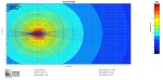
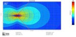
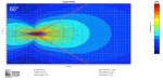
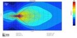
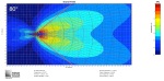
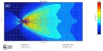
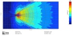
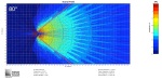
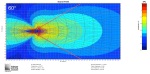
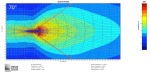
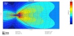
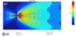
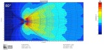
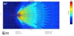
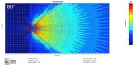
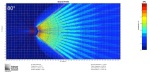
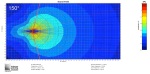
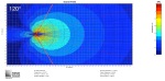
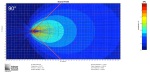
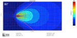
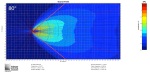
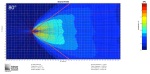
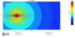
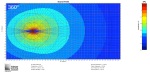
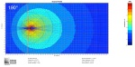
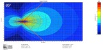
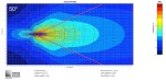
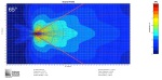
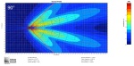
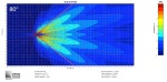
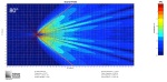
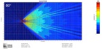
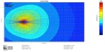
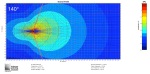
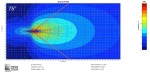
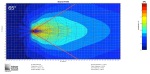
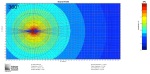
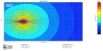
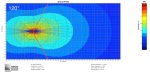
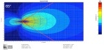
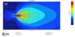
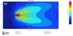
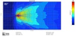
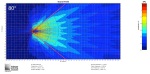
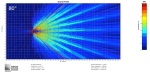
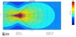
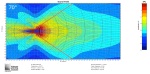
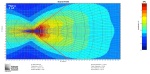
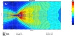
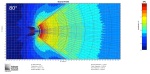
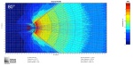
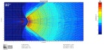
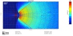
The diagram shows a concert room and a living room. The living room is in scale to the concert room. The light-shaded area in the living room drawing shows the area where the time difference between sources is less than 5 ms. This is the area where true stereo is achieved.

The same shading in the concert room is where one would assume you could obtain stereo imaging. The dark-shaded area shows the real area where stereo works properly in a concert room.

SIDE EFFECTS

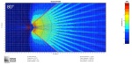
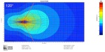
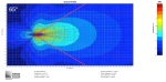
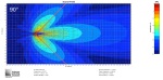
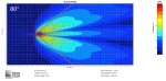
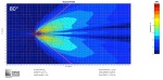
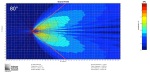
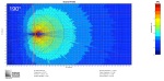
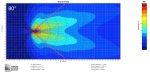
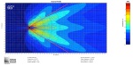
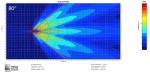
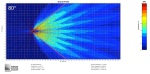
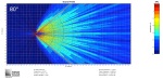
The search for a stereo image can have a negative effect in the frequency response uniformity if the speakers are arranged in a way where there is too many overlapping of coverage area.

Signals panned to the center, almost always the important channels, will arrive at different times to the seats far from the center. This causes severe comb filtering and changes the frequency response for each listener.

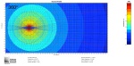
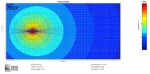
Comb filtering, or combing, is one of the side effects caused by combining signals that aren’t in sync. The time differences change the phase relation between both speakers for all the frequencies. In any location, the frequency response obtained will depend on the phase relation between both signals. When the phase matches, there will be a total sum. When the phase is inverted, there will be a total cancelation.

In any point in between those two, the combined signal won’t have sums or cancelations. Instead, it will have a series of audible peaks and depressions in the obtained response. Each change in location will hold different time differences between left and right channel, and because of this, a new phase relation, resulting in a new series of peaks and depressions in the frequency response.

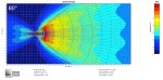
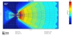
The irregularities caused by combing are more severe when you have two signals with the same intensity but different time arrival.

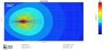
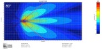
The more you try to spread the stereo, increasing the overlapping area of the speakers, the more audible will the peaks and dips will be. This is not to be taken lightly. A sound system with a large overlapping area will have variations of up to 30 dB in the frequency response over a band width that changes from seat to seat, turning EQ into something completely arbitrary. A short 1 ms delay will create a 1-octave hole in 500 Hz and will scale that way. Longer delays degrade the intelligibility and the sound quality even further.

If the stereo image is the most important, then you should fully pan the channels and make the overlapping coverage area of the speakers fill the room. The only way to beat time difference is forcing it with intensity. Although this expands the stereophonic area, you will be left with terrible level differences between channels at both sides of the room. However, channels panned to the center will have a variable response over the listening area, caused by the combing obtained with all the overlapping.

This technique was used for many years by a nameless touring band, which hard-panned several of its musicians. In the center of the listening area, the stereo was fantastic.

However, fans that couldn’t arrive early to the shows, in order to get seats in the center, would have to choose between listening to the left drummer and the guitar player, or, the right drummer and the keyboard player.

If the priority is to make the entire band enjoyable for the whole audience (and I expect it to be this way), then, leave the stereo as a special effect. Design the sound system in a way that the overlapping of the left and right speakers roughly matches the 5 ms time delay window area. Reduce the level of infill speakers so the front and center coverage can be achieved without big overlapping spaces. Don’t waste your time, energy and money on stereo delays and fills.

CONCLUSION

All of these can sound radical, maybe even heretical to many readers. After all, we have put too much time and effort into stereo reproduction in P.A systems.

It would be awesome if we could achieve stereo in every seat of the room, or even half of them. If a large amount of the audience receives the benefits of stereo imaging, we could argue that combing and intelligibility loss are a reasonable price to pay for it. But it is futile and self-destructive to fight against the laws of physics and psychoacoustics and to pretend that we are experiencing stereo, when we are not. Remember our priorities.

It is unlikely that our customers will raise their voice because they don’t have enough stereo. They certainly will of course, if everything sounds like a telephone or can’t be understood, two of the most common results when searching for stereo on big shows.

Mono sound reinforcements seem like something we should have already discarded for something better, but they have a big advantage over stereo: They work.

This is not a statement that will please the emperor, or the band manager, but it does hold some truth: ”This system has such magic qualities that it’s capable of creating perfect mono imaging in every seat”.

So thank you Jose Luis.

Take the cable test: Can you hear the difference?

Posted March 2, 2011 by 6o6
Categories: Uncategorized

John Huntington put together a recording that allows you to see if you can hear the difference between star-quad and regular cable. Try it yourself. I did.

And then fill out the survey. I did. It takes only a short time. The more statistics John has – the better he can get to the bottom of this

Here is the link

Thanks

6o6

Fall Teaching Tour: Vilnius

Posted November 2, 2010 by 6o6
Categories: Uncategorized

This is the 3rd year in a row that I have done a set of SIM Seminar in the fall in Europe. In the previous years we did Montebaur Germany (2x) and London (2x) and Madrid (1x). This year we mixed it up with two new cities: Vinius and Berlin and a 3rd round of London.

Vilnius is the largest city in Lithuania. Lithuania (the country) has the same population as my home city (St. Louis) of 3 million people. St. Louis is famous for bad beer. In Lithuania they prefer stronger stuff!

My host company was Ogmios Pulsas and I was well taken care of by Ramunas and Vitius. They showed me around the city and we tested out numerour restaurants, live music clubs, drinking spots, Ramunas’ house and almost…………..the local strip club by the hotel. It seems we did not drink QUITE enough to get there.  The class was quite full and included important engineers from Lithuania, Latvia, Estonia, Poland, Finland, Russia and more. Peoplpe were very focused on the subject at hand. It is amamzing what a difference the years make. It was not so long ago that I would stand in front of a bunch of folks and the message I got back was “Why can’t we just do it by ear?’  Nowadays a seminar is filled with folks who understand the power of the modern analyzer – and whether they use SIM, or one of the many Sons of SIM they are using the dual channel FFT – and they want to know how to do it better. I no longer have to convince people that using their ears AND an analyzer is the best combination for dealing with this VERY COMPLEX subject.

I really enjoyed everybody there. We had a great time at Ram’s house, eating, drinking and playing Jazz (and a bit of Rock’n’roll).  Thanks so much and I hope to come back there soon.

Ramunas - my host for the week

Vitius aught me lots about Vilnius history and culture... including an advanced drinking seminar

Hands on time at the SIM3

This is where we can see which students were on Facebook instead of SIM

This is Stephan Kruppa. He does all the hard work to make my seminars easy for me. He also thinks that is a drum in his hand.

Morristown Community Theater SIM3 Tuning

Posted September 21, 2010 by 6o6
Categories: Uncategorized

This has been a busy week for tunings. in an 8 day period I am scheduled to do two jobs: Morristown Community Theater and Carnegie Hall. The Morristown job is done and I am half way through Carnegie at this moment. The Morristown system was a really interesting tuning. It was a room/system that had everything you might encounter in the field. Left/Right mains were 15 box Line arrays in 3 segements (A-B-C) There were frontfills, underbalcony fills, an overbalcony fill, infills, outfills, a center downfill and subs. The room is a heritage 1920’s vintage art deco movie house which limited the placement options. Everyone there was great to work with. I was invited by Jonathan Peirce to get it done in two days. we definitely filled those days up.

I got crappy photos – but good SIM data and both will follow after I get done with Carnegie.

Sound System: Design & Optimization hits 10,000

Posted September 13, 2010 by 6o6
Categories: Sound Systems Book

Thanks for your support

I am grateful to announce that Sound Systems: Design & Optimization has reached the milestone of 10,000 copies sold. Around half of these are the English language editions and the remaining half split equally between the Spanish and Chinese language editions. Work is currently underway to translate the 2nd edition into Chinese. I want to extend my thanks to everyone that has supported this project, either by buying the book, promoting it to others, or helping me write it. Thanks especially to my editor Catharine Steers at Elsevier, all of my peer reviewers and those that contributed photographs and perspective pieces for the book. Thanks also to John and Helen Meyer, Gavin Canaan, Mac Johnson and all the staff there that continue to support my educational efforts through their sponsorship of my seminars and to all who have taken their valuable time to attend them. Thanks also to everyone at LiveDesign, Rational Acoustics, TC Furlong, and others that have helped promote this book.  Also to Ana Lorentz for translation of the Spanish Edition and to Magu for his help in that effort. Finally my highest gratitude goes to my wife Merridith who negotiated the deal and was one of just two people (along with Thorny) to read the whole book during its development.

When this was written I felt that less than 1250 books would be a failure, and anything more than 2500 would be a success. Reaching 10,000 in less than 4 years is far beyond my wildest dreams.

So thanks a million, I mean a ten thousand.

Sincerely,

 6o6

 In case you are interested: Here is what I did with the proceeds from the book: I crossed back over the art/science line to a 1978 Gibson Johnny Smith, and a 2009 Breedlove Bossa Nova.

1978 Gibson Johnny Smith

Breedlove Bossa Nova

Toning Your Sound System

Posted September 10, 2010 by 6o6
Categories: Alignment & Design, Analysis tools, FFT Analyzers, Tuning Techniques

No this is NOT a typo. I did not mean to write “Tuning your sound system” because that is entirely a different subject. So what is the difference between toning and tuning?

 Here is a simple example from the muscial side: This is my son Simon. He has a guitar effects pedal that has exactly the TONE of Eddie Van Halen. One small thing though: he can’t TUNE his guitar.

A legend in his own mind


Sound systems also have a similar contrast between these two concepts. Tuning  a sound system (in my estimation) is where you adjust the system so that it has uniform response over the listening area, with minimal distortion, maximum intelligibility and best available sonic imaging. Tuning is about making the far seats similar to the near seats. An objectively verifiable – but verifiably unattainable goal of same level, same frequency response, same intelligilbility throughout the room. Making the underbalcony as similar as possible to the mix position (which hopefully is NOT under the balcony). It is about making sure every driver is wired correctly, still alive, aimed at the right place and cleanly crossed over to the next one. It is about making it so the mix engineer can mix with confidence that theirs is a SHARED experience. Because it an objective pursuit, the use of prediction tools, analysis tools and our ears all play important roles in the process.  It does NOT, however mean that it sounds GOOD. “Good” is subjective.

Toning, on the other hand, can’t be done wrong. It is entirely subjective. Toning a system is the setting of a bank of global equalization filters at the output of the mix console that drives the sound system. If you want to set it by ear fine. If you want to set it by 10,000 hours of acoustical analysis containing mean/spline/root squared/Boolean averaging then go for it. If I am the mixer and I don’t like it, I will change it. Too bad. I like MY tone better. Deal with it. I don’t like flat. Deal with it. I like flat. Deal with it. There is nothing at stake here. Nothing to argue about. And no need to bring objectivity, or an analyzer to the table. The global equalizer is just an extension of the mix console eq. In the end the mixer will choose what they want to eq on a channel by channel  basis and what they want to eq globally. But also in the end there is no wrong answer, because it is entirely subjective. I have worked shows where, in my opinion the mix sounded like a cat in heat. That’s my opinion, and therefore not relevant, unless asked for. I asked the mixer “Are you happy with that?” They say “Yes”.  As long as I have ensured the cat in heat is transmitted equally to everybody in the room (i.e. TUNING the sound system), my work is done.

Good toning enhnaces the musical quaility, or natural quality of transmitted sound. Good tuning ensures that the good (or bad) toning makes it beyond the mix position.

 Piano Tuning…. and Toning

One does not have to know how to play a piano to be a competent piano tuner. It is an objective pursuit. Numbers. It can be done with an analyzer and/or a trained ear. The toning of a piano, a subjective paramater, cannot be wrong. John Cage opens up the piano and scatters nuts and bolts on top of the strings. This “tones” the piano. Is it wrong? Of course not. But before John Cage plays the “prepared” , i.e. toned piano, do you think he has it TUNED?  You bet.

John Cage Prepared Piano - a subjectively "toned" piano

 Below is another example of a “toned” piano.

I always wanted to find a way to work a deer head into my music

 Below are the tools for TUNING a piano. Similar to the ones we find our artistic auto mechanics using to TUNE up our car.

Tuning Forks

Hmmm..... Digital calipers: Objective or subjective?

Strobe tuner: otherwise known as a frequency analyzer


Just semantics or more?

So why do I make this distinction?  Because I have recently experienced several cases where people are confusing these concepts. In one case a guy wrote an article about how much better systems sound if they don’t have a flat response. Better to have peaks and dips. He notes that people that tune sound systems with analyzers do the clients a disservice by making thr system “flat”. Who am I to argue with this. He doesn’t like flat. OK. However, in the course of putting down acoustic analyzers for global equalization, the article never mentions the OTHER things that we use analyzers for: checking polarity, aiming the speakers, adjusting splay angles, adjusting relative level between speakers, setting crossovers, phase alignment, intelligibility analysis, treating reflections or most importantly: working to make it sound uniform throughout the room. The article compares equalizing your church sound system to your home hi-fi, which is to say TONING the system.  Maybe this guy’s approach is great for toning the system, but it is useless for tuning the sound system. The article “The fallacy of a flat system” can be found here

———————-

Then I received a question from one of my recent students from Asia:

Dear Bob:

Last week I join the BRAND X SPEAKER COMPANY seminar, they use another method to alignment the line-array system.

1) the whole line-array should be same EQ & same level.

2) they use room capture software to alignment the line-array system. They capture about 15 trace at difference mic position in the venue but not on axis speaker position and finally they sum average of the trace to 1 result then EQ it. What do you think?

————–

This was my reply:

1) the whole line-array should be same EQ & same level. 

I cannot find any good reason for this. The lower area is covered by the lower boxes, the upper area by the upper boxes. They are in very different acoustic environments, they are very much at different distances. Why lock yourself into a solution with no flexibility? If the end result is a perfect match… then great. If not…what can you do besides make excuses?

2) they use room capture software to alignment the line-array system. They capture about 15 trace at difference mic position in the venue but not on axis speaker position and finally they sum average of the trace to 1 result then EQ it. What do you think?

This solves NOTHING. The end result is the same eq to all speakers. If it was an average of 2 positions or 20,000 positions the average is still just ONE set of parameters. If it sounds different in the front than the back before you average then it will sound exactly the same amount different AFTER the average. Why bother to take samples all around the room if you are not going to do anything about the DIFFERENCES around the room? It is just a waste of time.

The only reason to use an analyzer is to get objective answers such as: is it the same or different?  Not for subjective ones such as – does it sound good?

Example: Let’s say you average 20,000 seats and put that in as the eq for all speakers. Then the mixer hears it and wants a boost at 2 kHz.  What are you going to do? You are going to boost 2 kHz or get fired. Who cares about the average now?

6o6

———-

In this case a manufacturer is using toning techniques without dealing with the tuning part. BOTH must be applied if we are going to bring the tonal experience to the people that pay to hear our sound systems.

Conclusion:

Keep an eye on both sides of the issue, but bring the right tool for the job:

Recommended system tuning attire

System toning outfit (Women only PLEASE!)


Toning apparel for men